EGR 224/Circuit Building and Measurements
Jump to navigation
Jump to search
$$ \newcommand{\E}[2]{#1_{\mathrm{#2}}} $$ This page will contain some tips and pictures for the EGR 224 Labs on Circuit Building and Measurements. It has been updated for Spring 2022.
Schematics
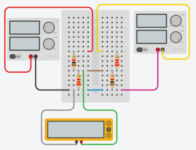
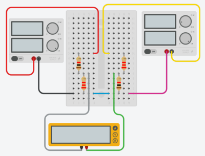
These are Tinkercad representations of how you should build your physical circuits. Your wiring should generally match these.
- The top left resistor is $$\E{R}{1ka}$$ and the bottom left resistor is $$\E{R}{2.2ka}$$.
- The top left source is the positive voltage source from the powered bread board (PBB) - the black wire is the ground wire and the red wire is the positive voltage wire. The top right source represents the negative voltage source from the PBB and the yellow wire represents that negative voltage. The pink wire will not actually physically exist on your circuit; both the positive and negative sources on the PBB are connected the same ground but Tinkercad actually needs two separate connections.
- The brown wire in the top picture may be orange for you; it is meant to connect the subnode attached to $$\E{R}{1ka}$$ and $$\E{R}{2.2ka}$$ to the subnode attached to $$\E{R}{1kb}$$ and $$\E{R}{2.2kb}$$; it is the wire through which $$\E{i}{y}$$ flows. In the second figure, note that the wire has been replaced by the multimeter in ammeter mode.
- The blue wire in the figure may be purple for you - it is meant to connect the ground of the PBB and the bottom of $$\E{R}{2.2ka}$$ to the bottom of $$\E{R}{1kb}$$; the negative voltage source is internally connected to the same ground as the positive voltage source (which is why the pink wire in the drawing will not show up in your circuit).

