Python:DAQ 1
This page contains pictures and graphs related to Data Acquisition Laboratory 1 (DAQ 1) of EGR 103. It was updated in Fall, 2019, to change the language to Python and revise pictures and descriptions. It was further updated for Spring, 2020, to use nidaqmx instead of PyDAQmx.
Contents
Supporting Pundit Pages
Getting Started
This lab will be done in groups of 2 (possibly one group of 3). Each group needs to take one of the large plastic boxes from the front of the room. Check the inventory when you get the box:
- One breadboard
- One screwdriver
- Four resistors (either yellow-purple-brown-gold or blue-gray-brown-gold)
- Five LEDs (red, yellow, green, blue, white)
- Ten wires (red, orange, yellow, green, blue, purple, black, gray, brown, white)
If anything is missing or if you have anything extra, let a TA know.
Typographical Errors / Clarifications
- When you are about to leave the lab, please be sure to completely log out of the computer - the DAQ systems will not work if multiple people are logged on to the same computer.
- If the computer says your device is not found, try 'Dev2' instead of 'Dev1' in the
#%% Add digital output lines
task.do_channels.add_do_chan("Dev1/port0/line0:2")
- line.
- If the you run the code and get an error:
DAQError: Specified operation cannot be performed while the task is running.
- or
DAQError: Requested operation could not be performed, because the specified digital lines are either reserved or the device is not present in NI-DAQmx.
- that generally means you had a task running and did not get a chance to stop it. To troubleshoot that, clear the variables by clicking the black and white eraser rhombus to the right above the IPython console. That generally removes all tasks so you can try again.
Module Installation
The NiDAQmx module is not automatically installed with Anaconda. However, it has probably already been installed on the PC in the lab. To check, start Spyder and then in the console type
- import nidaqmx as daq
If that works, you can skip the next step. If it does not work, close Spyder and then do the following:
- From the Start menu, find the Anaconda3 folder
- In the Anaconda3 folder, start the Anaconda Prompt
- In the Anaconda Prompt, type
pip install nidaqmx
Once the installation is done you can then restart Spyder and the import should work.
Equipment Used
National Instruments Data Acquisition Cards


B209 has machines with two different data acquisition cards. Most of the machines have NI PCI 6014e cards, which will be what is discussed here. The others have a newer NI PCI 6221 cards. The NI PCI 6014e card can read up to 16 single-ended (8 differential) analog voltage measurements, has two analog outputs, and has 8 configurable digital input/output lines. The 6221 cards are more powerful but, generally in EGR 103, we will limit ourselves to the features available on the 6014e cards.
Be careful when making connections; improperly connecting wires can lead to catastrophic damage on the DAQ cards, as is shown on the second picture at right.
CB-68LP

During this lab, you will use the CB-68LP to connect wires to parts of the NI PCI 6014e card. Be sure to use the proper connections - a map is available at the CB-68LP Pinout page.
Radio Shack Experimentor 350


The Experimentor 350 is a simple, but useful, prototyping board. It has two distribution strips (rows X and Y) with 20 pins each and 46 groups of 5 pins on its terminal strip. All the pins in row X are connected together, and all the pins in row Y are connected together; note, however, that X is not connected to Y. The actual Experimentor 350 is pictured right with a graphic below it showing how some of the pins are connected. Row X is the red row at the top and row Y is the blue row at the bottom.
For the main part of the board, half-columns are connected together. For example, rows (ABCDE) in the first column are all connected. Rows ABCDE are not connected to FGHIJ, however - in the graphic, ABCDE in column 1 are in yellow while FGHIJ in column 1 are in green. Furthermore, columns are not connected together.
There are some helpful index numbers at the top and bottom to help determine which column you are in. For rows X and Y, some indices do not exist. For example, there is no pin at X6, X12, X18, Y6, Y12, or Y18. The pin furthest right in those rows will still be called X23 or Y23, respectively.
Resistors

Resistors take energy out of an electric circuit and convert that energy to heat. In this case, the light emitting diodes cannot handle the amount of current that the DAQ card can produce, so resistors are placed in parallel to reduce that current. You can use the Resistor Color Codes to determine the resistance of the resistors pictures at right; there should be four resistors (at least) in your box and they should all have the same resistance values (even if they are different shapes and physical sizes).
LEDs


A diode is an electrical element that generally only allows current to flow in one direction - and only after there is a sufficient voltage difference across the appropriate terminals. LEDs - Light Emitting Diodes - are a special form of diode that emit light when current flows through them.
Because diodes and LEDs are directional, there are visible clues about which side is which. In the first picture at right, the lengths of the leads on the diodes are clearly different - the longer lead should be placed where the higher voltage is expected, as current will be allowed to flow into the longer lead, through the diode, and out through the shorter lead. For the round LEDs, a flat is ground into the collar of the LED on the lower-voltage side - this is shown more clearly in the second picture. Finally, within the diode itself, the larger "flag" of metal inside the diode is on the lower voltage side.
Note that the color of the plastic is not what determines the color of the light - rather the specific semiconductor material and the geometry of the LED do that. The plastic is a convenient way of knowing what color the light will be, however.
Circuit Construction
The pictures below show both the breadboard and the CB-68LP once everything has been properly connected. The first set of pictures is for the 3-bit circuit and the second set is for the 4-bit circuit. This version of the circuit uses four 390$$\Omega$$ resistors; the circuit you build should have four resistors of the same value between 390$$\Omega$$ and 1000$$\Omega$$.
Note where the wires are - on the breadboard, there is no connection to row X; the red, yellow, green, and eventually, blue wires are all in row A. On the CB-68LP there is be no connection in the first two columns and there is only one connection - the black wire for digital ground - in the fifth column.
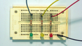
3-bit circuit on breadboard.
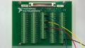
3-bit circuit connections to CB-68LP.
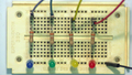
4-bit circuit on breadboard after adding extra wire, resistor, and light to the first column of the breadboard.
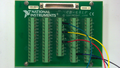
4-bit circuit connections to CB-68LP after adding extra wire for DIO3 or DIO3P0; use CB-68LP_Pinout to figure out where that is on the CB-68LP.


.svg)
Code
The following code listing is for three_bits.py In lab, do not put all this code in at once! Follow along, save the code after each section, and run it.
Imports
To access the functions to work with the DAQ card, you will need to import the nidaqmx module. Start your code with:
1 # %% Import modules
2 import nidaqmx as daq
If you correctly installed the nidaqmx module, your code should now run (though it will not do much else).
Create a Task
DAQ functions are run via a Task object, so next you will tell the daq module to create a task:
4 # %% Create a task
5 task = daq.Task()
Adding Lines
This part of the code will use the do_channels.add_do_chan() method on your task object to open digital output channels on the card specified in the first argument. Specifically, the card is Dev1 and on that device, the first bank of digital output lines is on port0. Within port 0, there are up to 8 lines - this code opens lines 0 through 2 (0:2). Note that unlike most parameters in Python, the 0:2 includes the 2.
7 # %% Add digital output lines
8 task.do_channels.add_do_chan("Dev1/port0/line0:2")
After you add this code and run your program, type
task.do_channels[0].physical_channel
in the console; Python should report back the three physical channels that have been created.
Checking Lights
Before doing anything interesting with the code, you will want to make sure all the lights are working. The following code will first turn the three lights on then it will wait for you to provide an input (you can just hit return). After that is done, it will turn the lights off.
10 # %% Check lights
11 task.write(7)
12 input("PAUSED - Hit return to continue ")
13 task.write(0)
If one or more of your lights fails to come on, carefully check the wiring. Note that the wires themselves are all in row A, not row X. Also make sure the longer lead of the LED is in row J.
Updating and Lighting Values
This part of the code will start by turning the lights off, then it will ask the user for an input. The code converts that input to an integer (since input always returns strings) and sends that value to the task.write() method.
15 # %% Write values to output using base 10
16 val = 0
17 while 0 <= val <= 7:
18     task.write(val)
19     val = int(input("Enter a number between 0 and 7: "))
When testing this part, be sure to enter a 0 before entering a value that exits the loop - this will turn the lights off before exiting the program; the next code section will take care of that regardless of the last valid number entered.
Cleaning Up
When the program is done, it should turn all the lights off and then stop the task.
21 # %% Turn all off when finished and stop task
22 task.write(0)
23 task.close()
Full Code
Here is what the code will eventually look like:
 1 # %% Import modules
 2 import nidaqmx as daq
 3
 4 # %% Create a task
 5 task = daq.Task()
 6
 7 # %% Add digital output lines
 8 task.do_channels.add_do_chan("Dev1/port0/line0:2")
 9
10 # %% Check lights
11 task.write(7)
12 input("PAUSED - Hit return to continue ")
13 task.write(0)
14
15 # %% Write values to output using base 10
16 val = 0
17 while 0 <= val <= 7:
18     task.write(val)
19     val = int(input("Enter a number between 0 and 7: "))
20
21 # %% Turn all off when finished and stop task
22 task.write(0)
23 task.close()
Other Resources
- Landing Lights Movie (old circuit without colorful wires or blue LEDs):

- Landing Lights Animation (based on Tinkercad simulation):

Questions
Post your questions by editing the discussion page of this article. Edit the page, then scroll to the bottom and add a question by putting in the characters *{{Q}}, followed by your question and finally your signature (with four tildes, i.e. ~~~~). Using the {{Q}} will automatically put the page in the category of pages with questions - other editors hoping to help out can then go to that category page to see where the questions are. See the page for Template:Q for details and examples.