Multisim/Divider
$$ \newcommand{\E}[2]{#1_{\mathrm{#2}}} $$
This page will contain a tutorial on building and analyzing a voltage divider in Multisim.
Contents
Multisim
Go to www.multisim.com to log in to your account.
Building Your Circuit
For this example, we are going to look at a voltage divider. To build this circuit in Multisim, you are going to create a schematic of your circuit and use measurement probes to take voltage and current measurements. To begin, click the CREATE CIRCUIT button on the top right of the screen.
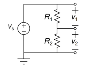
The schematic for the circuit you will be building is:
where $$\E{v}{s}$$ will be set by the power supply and $$\E{R}{1}$$ and $$\E{R}{2}$$ will be a matched pair of resistors. Ideally, this voltage divider will split the voltage from the supply exactly in half. You will be measuring the voltage drop across the bottom resistor ($$v_2$$).
Getting Parts
To start, on the left side of the Multisim window, there are several categories of elements to choose from. They are:
- Analysis and annotation (measurement probes)
- Schematic connectors (ground, connectors, junctions)
- Sources
- Passive
- Analog
- Diodes
- Transistors
- Indicators
- Switches
- Modeling blocks (controlled sources)
- Electromechanical
- Power
- Digital
You will need the following:
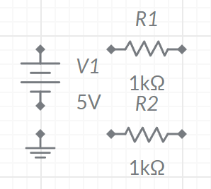
- Ground node (Schematic connectors)
- Two resistors (Passive)
- Voltage source (Sources)
Your canvas should resemble:
Building a Voltage Divider
Now you are going to build the voltage divider. If you need to rotate an element, you can click on it and type <shift> R or you can click the rotate icon at the bottom left of the context icons that come up. To create a wire, click a node on an element and drag the spool of wire to where you want it to go, clicking wherever you want the wire to make an angle and finally clicking on the other node or wire you want it to end at. You may want to spread the elements out a bit so the labels do not interfere with each other. Your canvas should resemble:
though the node numbers may be different depending on what order you used in connecting wires.
Adding Measurements
Add a voltage probe to the left side of $$R_1$$ by going into the Analysis and annotation group and choosing a Voltage probe. This defaults to measuring the voltage at that node relative to ground, but we actually want to measure the voltage relative to the bottom of that resistor. Click on the probe and the click on the V- option. This allows you to pick a reference node. Pick the node at the ride side of $$R_1$$. Your canvas should resemble:
Next, add a Voltage and current probe to the node between the resistors. Make sure the current probe is measuring the current going from top to bottom. You will not need a voltage reference node here since the bottom of $$v_$2$ is the ground node. If the labels overlap each other, that is fine; you can also make your circuit take up more space if you want everything to be clear with no overlapping labels. Your canvas should resemble: <center> [[File:Multisim0204.PNG|300px]] </center> =='"`UNIQ--h-5--QINU`"' Run the Simulation == Now that you have built the circuit and added the probes, you can run a simulation. Set the simulation type to DC Op by clicking the simulation type drop-down (it defaults to read '''Interactive''') and click the play button. You should get a reading of 6 V for each voltage and 6 mA for the current based on the default values for the components. In Tinkercad, we used 5 V for the source so go ahead and make that change. Note that when you change values in a circuit the probes will tell you their values are out of date. Re-run the simulation and you should now be reading 2.5 V across each resistor and 2.5 mA. <center> [[File:Multisim0205.PNG|300px]] </center> =='"`UNIQ--h-6--QINU`"' Notes == Multisim has powerful tools for analyzing a circuit as sources' values change, but nothing to automatically examine what happens as resistances change. Furthermore, the voltage probe is ''not'' simulating a multimeter - it does not include an internal resistance. Increase the resistors to 100 G$$\Omega$$ and run the simulation again. You will end up getting a voltage measurement different from the 2.5 V expected, but that is a computational issue rather than a feature of the simulation.


