EGR 103/DAQ 2
This page contains pictures and graphs related to Laboratory 6 (DAQ 2) of EGR 53.
Contents
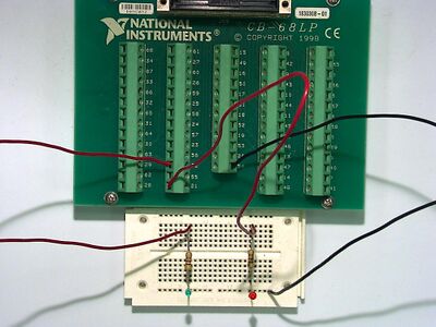
Circuit for BasicAOutput
Circuit layout for BasicAOutput.
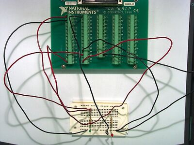
Circuit for BasicAIO
Circuit layout for BasicAIO (two measurements).
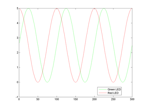
Graph from BasicAIO
Graph showing outputs when
Vout0 = 2.5+2.5*sin(2*pi*k/100);
Vout1 = 2.5+2.5*cos(2*pi*k/100);
That is,
\( V_{out,~0}=2.5+2.5~\sin\left(\frac{2\pi k}{100}\right)\\ V_{out,~1}=2.5+2.5~\cos\left(\frac{2\pi k}{100}\right) \)
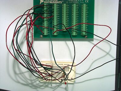
Circuit for AIO
Circuit layout for AIO (six measurements).
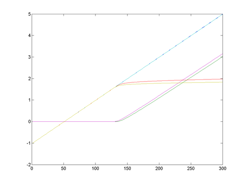
Graph from AIO
Graph showing outputs from six measurement channels.
Questions
Post your questions by editing the discussion page of this article. Edit the page, then scroll to the bottom and add a question by putting in the characters *{{Q}}, followed by your question and finally your signature (with four tildes, i.e. ~~~~). Using the {{Q}} will automatically put the page in the category of pages with questions - other editors hoping to help out can then go to that category page to see where the questions are. See the page for Template:Q for details and examples.
