Difference between revisions of "EGR 103/DAQ 1"
| Line 23: | Line 23: | ||
For the main part of the board, half-columns are connected together. For example, rows (ABCDE) in column 3 are all connected. Note, however, that ABCDE are not connected to FGHIJ. | For the main part of the board, half-columns are connected together. For example, rows (ABCDE) in column 3 are all connected. Note, however, that ABCDE are not connected to FGHIJ. | ||
| − | Also, there are some helpful index numbers at the top and bottom to help determine which column you are in. For rows X and Y, some indices do not exist. For example | + | Also, there are some helpful index numbers at the top and bottom to help determine which column you are in. For rows X and Y, some indices do not exist. For example: X6, X12, X18, Y6, Y12, and Y18 are not valid pin locations on these boards. |
<br clear=all /> | <br clear=all /> | ||
Revision as of 18:22, 7 October 2012
This page contains pictures and graphs related to Data Acquisition Laboratory 1 (DAQ 1) of EGR 53. It has been updated for Fall, 2009.
Contents
Equipment Used
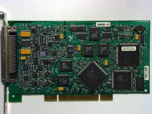
National Instruments PCI 6014e
The NI PCI 6014e card can read up to 16 single-ended (8 differential) analog voltage measurements, has two analog outputs, and has 8 configurable digital input/output lines.
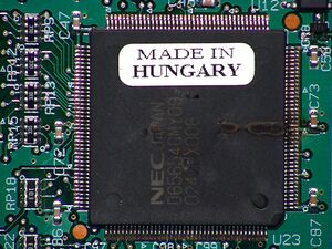
Be careful when making connections; improperly connecting wires can lead to catastrophic damage on the 6014e, as is shown on the second picture at right.
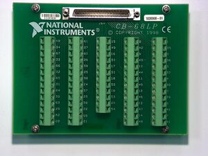
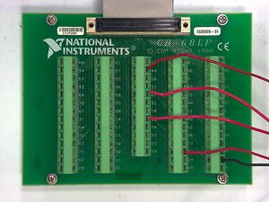
CB-68LP
During this lab, you will use the CB-68LP to connect wires to parts of the NI PCI 6014e card. Be sure to use the proper connections - a map is available at the MATLAB:CB-68LP Pinout page.
Radio Shack Experimentor 350
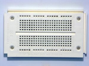
The Experimentor 350 is a simple, but useful, prototyping board. It has two distribution strips (rows X and Y) with 20 pins each and 46 groups of 5 pins on its terminal strip. All the pins in row X are connected together, and all the pins in row Y are connected together; note, however, that X is not connected to Y.
For the main part of the board, half-columns are connected together. For example, rows (ABCDE) in column 3 are all connected. Note, however, that ABCDE are not connected to FGHIJ.
Also, there are some helpful index numbers at the top and bottom to help determine which column you are in. For rows X and Y, some indices do not exist. For example: X6, X12, X18, Y6, Y12, and Y18 are not valid pin locations on these boards.
Resistors
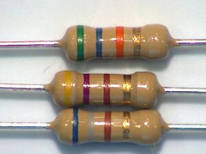
Resistors take energy out of an electric circuit and convert that energy to heat. In this case, the light emitting diodes cannot handle the amount of current that the DAQ card can produce, so resistors are placed in parallel to reduce that current. You can use the Resistor Color Codes to determine the resistance of the resistors pictures at right; there should be four resistors (at least) in your box.
LEDs

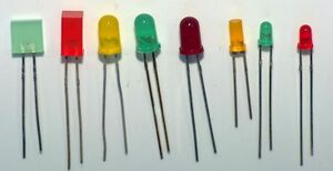
A diode is an electrical element that generally only allows current to flow in one direction - and only after there is a sufficient voltage difference across the appropriate terminals. LEDs - Light Emitting Diodes - are a special form of diode that emit light when current flows through them.
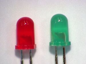
Because diodes and LEDs are directional, there are visible clues about which side is which. In the first picture at right, the lengths of the leads on the diodes are clearly different - the longer lead should be placed where the higher voltage is expected, as current will be allowed to flow into the longer lead, through the diode, and out through the shorter lead. For the round LEDs, a flat is ground into the collar of the LED on the lower-voltage side - this is shown more clearly in the second picture. Finally, within the diode itself, the larger "flag" of metal inside the diode is on the lower voltage side.
Note that the color of the plastic is not what determines the color of the light - rather the specific semiconductor material and the geometry of the LED do that. The plastic is a convenient way of knowing what color the light will be, however.
Circuit Construction
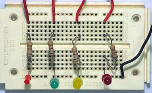
The pictures at right show both the breadboard and the CB-68LP once everything has been properly connected. Note especially on the CB-68LP where the wires are - there will be no connections in the first two columns and there is only one connection - the black wire for digital ground - in the fifth column.
Questions
Post your questions by editing the discussion page of this article. Edit the page, then scroll to the bottom and add a question by putting in the characters *{{Q}}, followed by your question and finally your signature (with four tildes, i.e. ~~~~). Using the {{Q}} will automatically put the page in the category of pages with questions - other editors hoping to help out can then go to that category page to see where the questions are. See the page for Template:Q for details and examples.
