Difference between revisions of "Tinkercad/Divider"
(→Building a Voltage Divider) |
|||
| Line 39: | Line 39: | ||
* Put a black wire between a21 and bot-21; this will ground the bottom of the vertical resistor | * Put a black wire between a21 and bot-21; this will ground the bottom of the vertical resistor | ||
| − | Drag the meters so the terminals are above the whole breadboard. We are going to be measuring the current through the circuit as well as the voltage drop across the vertical resistor. When measuring current, you measure | + | Drag the meters so the terminals are above the whole breadboard. We are going to be measuring the current through the circuit as well as the voltage drop across the vertical resistor. When measuring current, you measure ''through'' so the ammeter acts almost like a wire. Connect a gray wire from j17 to the left terminal of the right-hand multimeter, then connect a pink wire from the right terminal of the right-hand multimeter to j21. This means that the right side of the horizontal resistor is now electrically connected to the top of the vertical resistor. Finally, to measure the voltage drop across the vertical resistor, connect a purple wire from the right terminal of the left-hand multimeter to g21 and a brown wire from the left side of the left multimeter to bot-4. Start the simulation, then make sure the left meter is turned into a voltmeter and the right meter is turned into an ammeter. Your canvas should now resemble: |
<center> | <center> | ||
[[File:Tinkercad0204.PNG|400px]] | [[File:Tinkercad0204.PNG|400px]] | ||
| Line 45: | Line 45: | ||
If there are any issues with the circuit at this point, be sure to fix them before moving forward. Sometimes resistors do not fully attach to the breadboard. If you are getting no current through the circuit, first make sure your wires are in the right place. If they are, stop the simulation, then drag each resistor left and right or up and down and make sure it is affixing itself to a port on the breadboard (one of the resistor terminals will turn into a square if the resistor is going to connect to the breadboard). | If there are any issues with the circuit at this point, be sure to fix them before moving forward. Sometimes resistors do not fully attach to the breadboard. If you are getting no current through the circuit, first make sure your wires are in the right place. If they are, stop the simulation, then drag each resistor left and right or up and down and make sure it is affixing itself to a port on the breadboard (one of the resistor terminals will turn into a square if the resistor is going to connect to the breadboard). | ||
| − | |||
== Further Exploration == | == Further Exploration == | ||
There are some other features of Tinkercad to explore. Notice on the power supply that there are two knobs - the top knob sets the desired voltage and the bottom knob sets the current ''limit''. The supply will try to supply the required voltage, and if it can, you will see a green light to the top right of the voltage knob. To see what happens when this fails, go ahead and change both resistors to be 1 $$\Omega$$. The current is now 2.50 A coming out of the supply and measured as -2.50 A by the ammeter. Slowly increase the voltage until you get almost to 10 V, then keep going - you will notice that the voltage cannot increase past 10 V and that the light goes off by the voltage knob and turns on near the current knob. The power supply is no longer able to deliver the current needed to get the voltage past 10 V. Next, roll the '''current''' knob counter-clockwise and notice that both the current and voltage decrease based on the new current limit. | There are some other features of Tinkercad to explore. Notice on the power supply that there are two knobs - the top knob sets the desired voltage and the bottom knob sets the current ''limit''. The supply will try to supply the required voltage, and if it can, you will see a green light to the top right of the voltage knob. To see what happens when this fails, go ahead and change both resistors to be 1 $$\Omega$$. The current is now 2.50 A coming out of the supply and measured as -2.50 A by the ammeter. Slowly increase the voltage until you get almost to 10 V, then keep going - you will notice that the voltage cannot increase past 10 V and that the light goes off by the voltage knob and turns on near the current knob. The power supply is no longer able to deliver the current needed to get the voltage past 10 V. Next, roll the '''current''' knob counter-clockwise and notice that both the current and voltage decrease based on the new current limit. | ||
Latest revision as of 01:05, 2 February 2023
$$ \newcommand{\E}[2]{#1_{\mathrm{#2}}} $$
This page will contain a tutorial on building and analyzing a voltage divider in Tinkercad.
Contents
Tinkercad
Go to www.tinkercad.com to log in to your account.
Building Your Circuit
For this example, we are going to look at a voltage divider. To build this circuit in Tinkercad, you are going to place your components on a breadboard and use a virtual multimeter to take resistor, voltage, and current measurements. To begin, click the Tinkercad logo at the top left to get to the dashboard. Click on the + New button on the right side of the screen and create a new circuit.
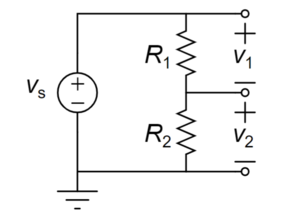
The schematic for the circuit you will be building is:
where $$\E{v}{s}$$ will be set by the power supply and $$\E{R}{1}$$ and $$\E{R}{2}$$ will be a matched pair of resistors. Ideally, this voltage divider will split the voltage from the supply exactly in half. You will be measuring the voltage drop across the bottom resistor ($$v_2$$).
Getting Parts
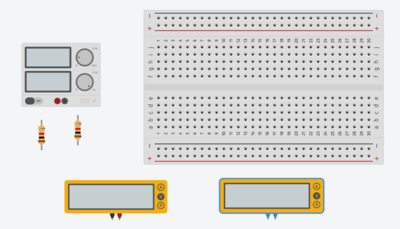
To start, on the right side of the Tinkercad window, set the Components drop-down box to Basic. If you scroll through, you will see many basic circuit components are available. Drag a Breadboard Small, two Resistor, and two Multimeter from this list onto the design canvas. You will also want a power supply, which is not a part of the Basic components list. In the search box under the Components dropdown, type Power Supply and then drag a Power Supply onto the canvas. Your canvas should resemble:
Measuring Resistances
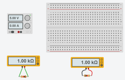
To take resistance measurements, you will want to connect the terminals of the multimeter to the terminals of the resistors with wires. This may be easier if the resistors are horizontal versus vertical; to rotate an element, select it and then press r to rotate clockwise or <shift> R to rotate counter-clockwise. Reposition the resistors so each one is under a different multimeter. Drag a wire from the terminal of one multimeter to one side of one of the resistors, then drag a wire from the other terminal of the same multimeter to the other wire. Do this for both multimeter-resistor pairs and start the simulation. You can make your connections as realistic as you want by having the wires bend or by changing the colors. Regardless, once you have made your connections, start the simulation. Since the meters are in voltmeter mode by default, both should be showing 0.00 V. To turn them into ohmmeters, click the R button on each meter. Your meters will now be showing the resistance value for each resistor, which will be 1.00 k$$\Omega$$ if you are using the default resistor. Your canvas should now resemble:
Building a Voltage Divider
Now you are going to build the voltage divider. Go ahead and stop the simulation, then delete the wires between the multimeters and the resistors. Move your power supply so it is to the right of the breadboard - this is just to make it easier to connect the positive terminal to the + rail at the top of the breadboard and the negative terminal to the - rail. Connect a red wire from the positive terminal to the top + rail (later called top+) and a black wire from the negative terminal to the bottom - rail (later called bot-). Adjust the bends in the wires so the circuit looks nice by double-clicking in a wire to create a new adjustable location; you can get rid of these extra locations by selecting the wire, then selecting the circle indicating the adjustable location, then clicking delete. Your canvas should now resemble:
Next, build the divider:
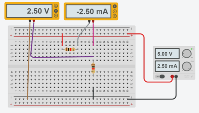
- Put a horizontal resistor between i13 and i17
- Put a vertical resistor between f21 and d21
- Put a red wire between top+13 and j13; this will deliver the source voltage to the horizontal resistor
- Put a black wire between a21 and bot-21; this will ground the bottom of the vertical resistor
Drag the meters so the terminals are above the whole breadboard. We are going to be measuring the current through the circuit as well as the voltage drop across the vertical resistor. When measuring current, you measure through so the ammeter acts almost like a wire. Connect a gray wire from j17 to the left terminal of the right-hand multimeter, then connect a pink wire from the right terminal of the right-hand multimeter to j21. This means that the right side of the horizontal resistor is now electrically connected to the top of the vertical resistor. Finally, to measure the voltage drop across the vertical resistor, connect a purple wire from the right terminal of the left-hand multimeter to g21 and a brown wire from the left side of the left multimeter to bot-4. Start the simulation, then make sure the left meter is turned into a voltmeter and the right meter is turned into an ammeter. Your canvas should now resemble:
If there are any issues with the circuit at this point, be sure to fix them before moving forward. Sometimes resistors do not fully attach to the breadboard. If you are getting no current through the circuit, first make sure your wires are in the right place. If they are, stop the simulation, then drag each resistor left and right or up and down and make sure it is affixing itself to a port on the breadboard (one of the resistor terminals will turn into a square if the resistor is going to connect to the breadboard).
Further Exploration
There are some other features of Tinkercad to explore. Notice on the power supply that there are two knobs - the top knob sets the desired voltage and the bottom knob sets the current limit. The supply will try to supply the required voltage, and if it can, you will see a green light to the top right of the voltage knob. To see what happens when this fails, go ahead and change both resistors to be 1 $$\Omega$$. The current is now 2.50 A coming out of the supply and measured as -2.50 A by the ammeter. Slowly increase the voltage until you get almost to 10 V, then keep going - you will notice that the voltage cannot increase past 10 V and that the light goes off by the voltage knob and turns on near the current knob. The power supply is no longer able to deliver the current needed to get the voltage past 10 V. Next, roll the current knob counter-clockwise and notice that both the current and voltage decrease based on the new current limit.


